再度PIC18F4550でLCDを動かす
2023/04/30

前回LCDの実験をしていたのが2017年で、もう6年前になるのである。
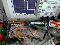
ブレッドボードにセットしたPIC18F4550とLCDは、当時実験していた回路が、ほぼそのままで埃だらけになっていたのである。
当時は、介護をしていた母親の体調悪化が止まり、なんだか良い感じになって、私の気分にも余裕が出てきた頃だったのである。
今は誰もいなくなり、自由と言えば究極の自由になっているのである。
ただ、人間(私は)ダメなもので、時間が無いときは「やりたいことがあるのに時間が無い!!、時間が欲しい!!」と、駄々をこねるのだが、時間が十分にあると、「明日出来ることは今日はしない」と、何もしなくなるのである。
頭の中はすっかりクリアされて空っぽ状態だったのだが、幸いなことにこのHPでプログラムと説明を書いておいたので、思い出すのが比較的楽なのである。
ただプログラムは、単純にコピペをしてしまうと、ほんのちょっとのトラブルでも理解出来ない状況になるので、それなりに理解しながらもう一度書いていく。
1、I2Cの制御プログラム
2、LCDの制御プログラム
3、メインのプログラム
まずはI2Cを制御するプログラムのヘッダーファイル
#include  // include processor files - each processor file is guarded.

void I2C_Master_Init(void);
void I2C_Master_Wait(void);
void I2C_Master_Wait2(void);
void I2C_Master_Start(void);
void I2C_Master_ReStart(void);
void I2C_Master_Stop(void);
void I2C_Master_Write(unsigned d);
unsigned char I2C_Master_Read(void);

#define _XTAL_FREQ 48000000     // 使用するPIC等により動作周波数値を設定する
                                // 水晶は20MHzでPLLで48MHz動作
次にI2Cを制御するプログラムの本体
#include
#include "I2C.h"

void I2C_Master_Init()
{
    SSPSTAT = 0b11000000;        //
    SSPCON1 = 0b00101000;        //SSP Module as Master
    SSPCON2 = 0;
//    SSPADD = 119;                //Setting Clock Speed 100KHz
//    SSPADD = 239;                //Setting Clock Speed 50KHz
    SSPADD = 149;                //Setting Clock Speed 80KHz
}

void I2C_Master_Wait()
{
  while ((SSPSTAT & 0x04) || (SSPCON2 & 0x1F)); //Transmit is in progress
}

void I2C_Master_Wait2()
{
  while(!SSPIF);                              //wait till SSPIF flag is set
    SSPIF=0;
}

void I2C_Master_Start()
{
  I2C_Master_Wait();
  SSPCON2bits.SEN = 1;             //Initiate start condition
  I2C_Master_Wait2();
}

void I2C_Master_Stop()
{
  I2C_Master_Wait();
  SSPCON2bits.PEN = 1;           //Initiate stop condition
  I2C_Master_Wait2();
}

void I2C_Master_Write(unsigned d)
{
  L1 : I2C_Master_Wait();
  SSPBUF = d;         //Write data to SSPBUF
  I2C_Master_Wait2();
  while(ACKSTAT)                              //check if acknowledgement signal received
    {
        I2C_Master_ReStart();                 //If no acknowledgement received, give restart signal and transmit data again
        goto L1;
    }
}

void I2C_Master_ReStart(void)
{
    RSEN=1;                                     //Initiate restart condition
    I2C_Master_Wait2();                         //Wait till completion of event
}

unsigned char I2C_Master_Read(void)
{
    RCEN=1;                                     //Enable reception in Master device
    while(!BF);                                 //Wait till buffer is full
    RCEN=0;                                     //Enable reception in Master device
    return SSPBUF;                              //return received data
}
LCD制御プログラムのヘッダーファイル
#include  // include processor files - each processor file is guarded.

#define LCD_ADDR          0xa0  // LCDのアドレス
#define LCD_CMD           0x00  // コマンド
#define LCD_DATA          0x80  // データ

#define LCD_CLEAR_DISPLAY 0x01  // LCDクリア
#define LCD_FUNCTION_SET  0x38  // 8ビットデータ、2行
#define LCD_DISPLAY_ON    0x0c  // ディスプレイオン
#define LCD_ENTRY_MODE    0x06  //
#define LCD_LOC           0x80  //

void lcd_init(void);
void lcd_cls(void);
void lcd_loc(unsigned char, unsigned char);
void lcd_putc(unsigned char);
void lcd_str(char *);
LCDの制御プログラム
#include "LCD.h"
#include "I2C.h"

void lcd_init(void)
{
    I2C_Master_Init();
    __delay_ms(5) ;        // 5ms

    I2C_Master_Start();
    I2C_Master_Write(LCD_ADDR);
    I2C_Master_Write(LCD_CMD);
    I2C_Master_Write(LCD_CLEAR_DISPLAY);
    I2C_Master_Stop();
    __delay_ms(5) ;        // 5ms

    I2C_Master_Start();
    I2C_Master_Write(LCD_ADDR);
    I2C_Master_Write(LCD_CMD);
    I2C_Master_Write(LCD_FUNCTION_SET);
    I2C_Master_Stop();
    __delay_ms(5) ;        // 5ms

    I2C_Master_Start();
    I2C_Master_Write(LCD_ADDR);
    I2C_Master_Write(LCD_CMD);
    I2C_Master_Write(LCD_DISPLAY_ON);
    I2C_Master_Stop();
    __delay_ms(5) ;        // 5ms

    I2C_Master_Start();
    I2C_Master_Write(LCD_ADDR);
    I2C_Master_Write(LCD_CMD);
    I2C_Master_Write(LCD_ENTRY_MODE);
    I2C_Master_Stop();
    __delay_ms(5);        // 5ms
}

void lcd_cls(void)
{
    I2C_Master_Start();
    I2C_Master_Write(LCD_ADDR);
    I2C_Master_Write(LCD_CMD);
    I2C_Master_Write(LCD_CLEAR_DISPLAY);
    I2C_Master_Stop();
    __delay_ms(5);        // 5ms
}

void lcd_loc(unsigned char x, unsigned char y)
{
    unsigned char addr;

    addr = y * 0x40 + x;
    addr = addr | LCD_LOC;
    I2C_Master_Start();
    I2C_Master_Write(LCD_ADDR);
    I2C_Master_Write(LCD_CMD);
    I2C_Master_Write(addr);
    I2C_Master_Stop();
}

void lcd_putc(unsigned char c)
{
    I2C_Master_Start();
    I2C_Master_Write(LCD_ADDR);
    I2C_Master_Write(LCD_DATA);
    I2C_Master_Write(c);
    I2C_Master_Stop();
}

void lcd_str(char *s)
{
    unsigned char i;

    for (i = 0; i < 16; i ++) {
	if (*s == 0) {
	    break;
	}
    I2C_Master_Start();
	I2C_Master_Write(LCD_ADDR);
	I2C_Master_Write(LCD_DATA);
	I2C_Master_Write(*s);
    I2C_Master_Stop();
	s ++;
    }
}
最後にメインのプログラム
//#include < stdio.h >
//#include < stdlib.h >
#include

#include "I2C.h"
#include "LCD.h"

// コンフィギュレーション pic18f4550  c18
#pragma config PLLDIV = 5, CPUDIV = OSC1_PLL2, USBDIV = 2
#pragma config FOSC = HSPLL_HS, FCMEN = OFF, IESO = OFF
#pragma config PWRT = ON, BOR = OFF, BORV = 0
#pragma config VREGEN = ON, WDT = OFF, WDTPS = 1
#pragma config CCP2MX = OFF, PBADEN = OFF, LPT1OSC = OFF
#pragma config MCLRE = OFF, STVREN = OFF, LVP = OFF
#pragma config ICPRT = OFF, XINST = OFF, DEBUG = OFF
#pragma config CP0 = OFF, CP1 = OFF, CP2 = OFF, CP3 = OFF
#pragma config CPB = OFF, CPD = OFF
#pragma config WRT0 = OFF, WRT1 = OFF, WRT2 = OFF, WRT3 = OFF
#pragma config WRTC = OFF, WRTB = OFF, WRTD = OFF
#pragma config EBTR0 = OFF, EBTR1 = OFF, EBTR2 = OFF, EBTR3 = OFF, EBTRB = OFF

int main(void) {

    unsigned char x;
    unsigned char y;
    unsigned char chr;

    TRISD = 0b00000000;			//PORTA=0-7 output
    TRISB = 0b11111111;			//PORTB=0-7 input
    LATD = 0;

    lcd_init();

    x = 0;
    y = 0;
    chr = 32;

    while(1){
        RD0 = 1;

        lcd_loc(x,y);
        lcd_putc(chr);
//        lcd_loc(1,1);      // I2C信号のテスト
//        lcd_putc('X');

        x = x + 1;
        if ( x > 15 ) {
            x = 0;
            y = y + 1;
            if ( y > 1 ) y = 0;
        }
        chr = chr + 1;
        if ( chr > 127 ) chr = 32;

        RD0 = 0;
        __delay_ms(200) ;        // ms
   }

    return (0);
}

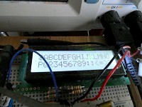
動作中のLCD
HOME

